Engineering Portfolio
The official course description:
An introductory course in computer graphics applications for mechanical- and aeronautical-related professions. Experiences focus on visualization, sketching, graphic standards, and problem-solving strategies for engineering design.
This course has taught me a great deal about the many useful tools found within the Siemens NX software. On this page, you will find the many different assignments and projects I have completed for the course.
Basic Modeling
This section contains all of the introductory CAD components I created while learning the basics of NX.
From left to right:
-
Rubber Seal: Used basic sketches and extrusions to create the base cylinder. Used the hole feature to create the center hole. Used the pattern feature to add the tabs on the seal.
-
Coupler: Basic sketches, extrusions, fillets, and constraints.
-
Stake: Used the edge blend feature to trace out the geometry seen.


4. Air Filter Cover: The left two images are of an air filter. I used fillets and chamfers to create half of the part and then used the mirror geometry feature to finish the whole object.
5. Caster Frame: Using the same tools as above, I created a caster frame as can be seen below.


Assemblies
This section contains all of the work that involved assemblies and the tools related to them:
1. Bearing Mount: The left two images contain a bearing mount assembly. Here I used premade parts to practice using the different assembly constraints.
2. Cart: The right two images contain a cart. Once again, I used premade parts to practice using the assembly constraints.


3. Spindle Assembly: Once again, I used premade parts to practice assembly constraints. I used the cross-section tool so it would be easier to see the various constraints I applied to the components.

Expressions
During the course, I learned how to use expressions to alter the dimensions of a model at any point. Below, you can see a component in which the dimensions have been altered and the expressions list containing the dimensions.


Legos/Part Families
A large focus of this course was on creating Legos with NX. This was because different sized Lego pieces are easily created by altering variables of a parent Lego part in which all of the fundamental components and patterns are defined. All of the pieces seen below are made from a single part family.


Below you can see the part family list in which all of the different variables are listed. The Legos pictured above are a compilation of the Legos listed in the part family below.

Using the part family from above, I created the Lego gate as a project. Please check out the PowerPoint presentation that covers the process from start to finish.

Other
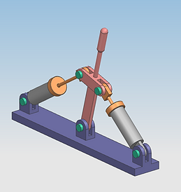
Arrangements: Using premade parts, I created the assembly below. Since this is a moving part, I needed to create views of the part in various arrangements.


Human Modeling: For an assignment, I experimented with the human modeling tool in NX. Here you can see multiple humans of different genders and sizes lined up.


Exploded View: Below you can see an exploded view of an assembly that contains a part list and balloons labeling the parts within the view.
