Engineering Portfolio
Over the summer of 2022, I worked as a Thermo-Chiller Engineering intern at SMC under my supervisor, Steve Simmons. It was a great experience working in industry and I enjoyed putting the knowledge that I have gained in school to use. This page covers two of the projects I completed during my time at SMC.
Here are the slides to the end-of-summer presentation I made at the end of my internship. Note that I added some captions to the images and had to blur some images that were at risk of exposing SMC's intellectual property.


Actual Lift
Lift I modeled in SolidWorks

Testing magnet strength
First concept
Second concept


Here are some schematics I made to describe the processes that this particular chiller undergoes.
Cool Gas


Our plan was to cut the tubes in half and then drill holes in them so we could install the LED strips inside of the tubes and have the light visible through the holes.


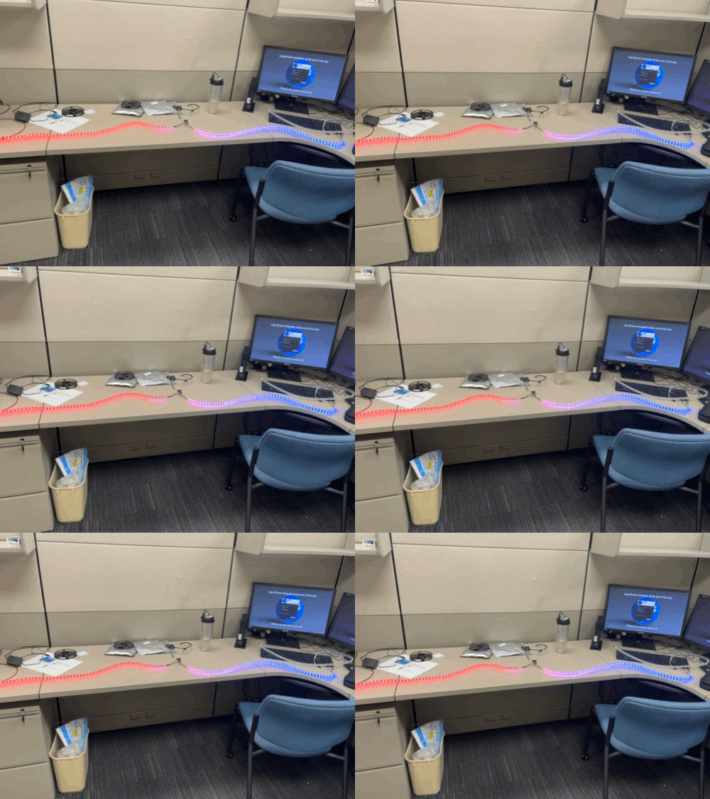
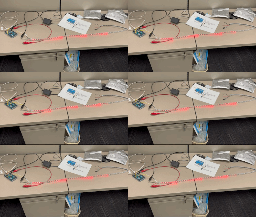
Here you can see my progression through learning how to program different lighting patterns.
In this step, my teammates took the expansion valve controller to a lab and discovered how it worked. Then, I was able to create a circuit to control the valves.
Here is my first attempt at soldering.
Below is my second attempt (with soldering flux).
It's difficult to see, but the valve is slowly opening in the video.

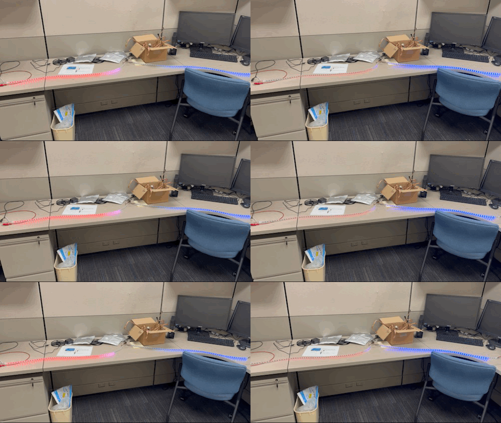
Here is a picture of the lights installed into the cut pipes. I didn't include any pictures of this in the original slides because I had the finished product in the room at the time of the presentation.
As you can see, the pipes are still intact on the side that we are viewing them and the lights shine through.
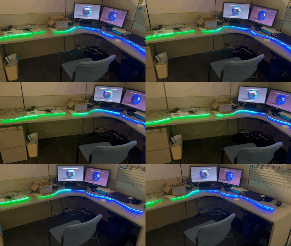
The LEDs represent the refrigerant's flow and temperature. The redder the color of the lights, the hotter the refrigerant is in the cycle. The bluer the color, the cooler the refrigerant. I was able to use the gradients to smoothly transition between hot and cool refrigerant when it flows through the heat exchangers.
I created the entirety of the code in Arduino IDE. It is fully functional, but there were definitely improvements that could have been made that would both simplify the code and shorten it. Unfortunately, the summer had come to an end before I was able to complete these optimizations.
Each of the highlighted segments represent parts of the code that completed different operations. These operations are commented above each segment.


