
Engineering Portfolio
ME 35401: Windmill Project
Course taken Spring 2023 semester
Official course description:
Physical experiments on static and fatigue failure of mechanical parts. Application of failure theories to design of mechanical components and systems. Open-ended design projects to reinforce the design process.
This course taught me a great deal about the lifecycle of a variety of materials and basic design principles to follow when creating a mechanical device. The final project for this lab was to create a windmill-style fan that is driven by an electric motor. Essentially, there was an electric motor connected to a gearbox which drove fan blades. There was a competition in class to create the windmill with the highest gear ratio such that the windmill blades would spin the slowest. My lab partner and I did not end up winning but we were a close runner up. Regardless, it was a great experience and I enjoyed completing this project.
Progress Reports
Progress Report 1
Progress Report 2
Progress Report 3
Final Report
For the most part, I worked on the CAD assembly while my partner worked on printing, assembling, and testing. Each time we iterated on a part, he would tell me what worked well and what needed changes. I was able to use parameters to make quick edits to the parts such as shaft or hole diameter for the gears and shafts, the spacing between gears, and the overall dimensions of the base.
Here, I will go more into the design work that went into this project.
Initial Concept
First, we decided on how we wanted to lay out our gear box. We agreed to move forward with this design where gears were put into pairs that shared a shaft. This shaft would be supported by a bearing. Each large gear was connected to a small gear on the other end of the shaft, allowing us to achieve the high gear ratio we were aiming toward.

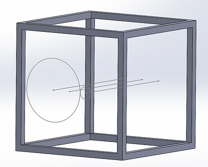
Initially, I wanted to create a frame in which we could mount all of our axles, gears, and any other devices. While this would look cool and allow for a variety of mounting options, we decided pretty early on that this was not the solution we were looking for due to its size and material consumption.
Base Plate
I began working on a new frame design and ended up with the one below.
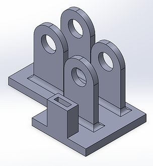
The rectangular extrusion at the front is where the motor is mounted and the pillars with holes is where the bearings and shafts for the gears are inserted.
Gears
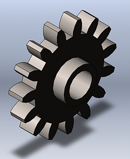
Our idea for the gears was that we would pair up gears and connect them with a shaft for each pillar. We planned to have the shaft attached to one of the gears in the pair and then connect the other gear without the shaft to the one with the shaft.
We used two sizes of gears, 15 tooth and 50 tooth. You can see these below.

Turbine
The turbine for this project was entirely cosmetic and served no real functional purpose. I just followed a simple tutorial online to create this.

Final Assembly
After printing out each part and then iterating until all of the fits worked, we created the final assembly and tested it.


